FSAE Kinematics
Formula SAE Suspension Kinematics
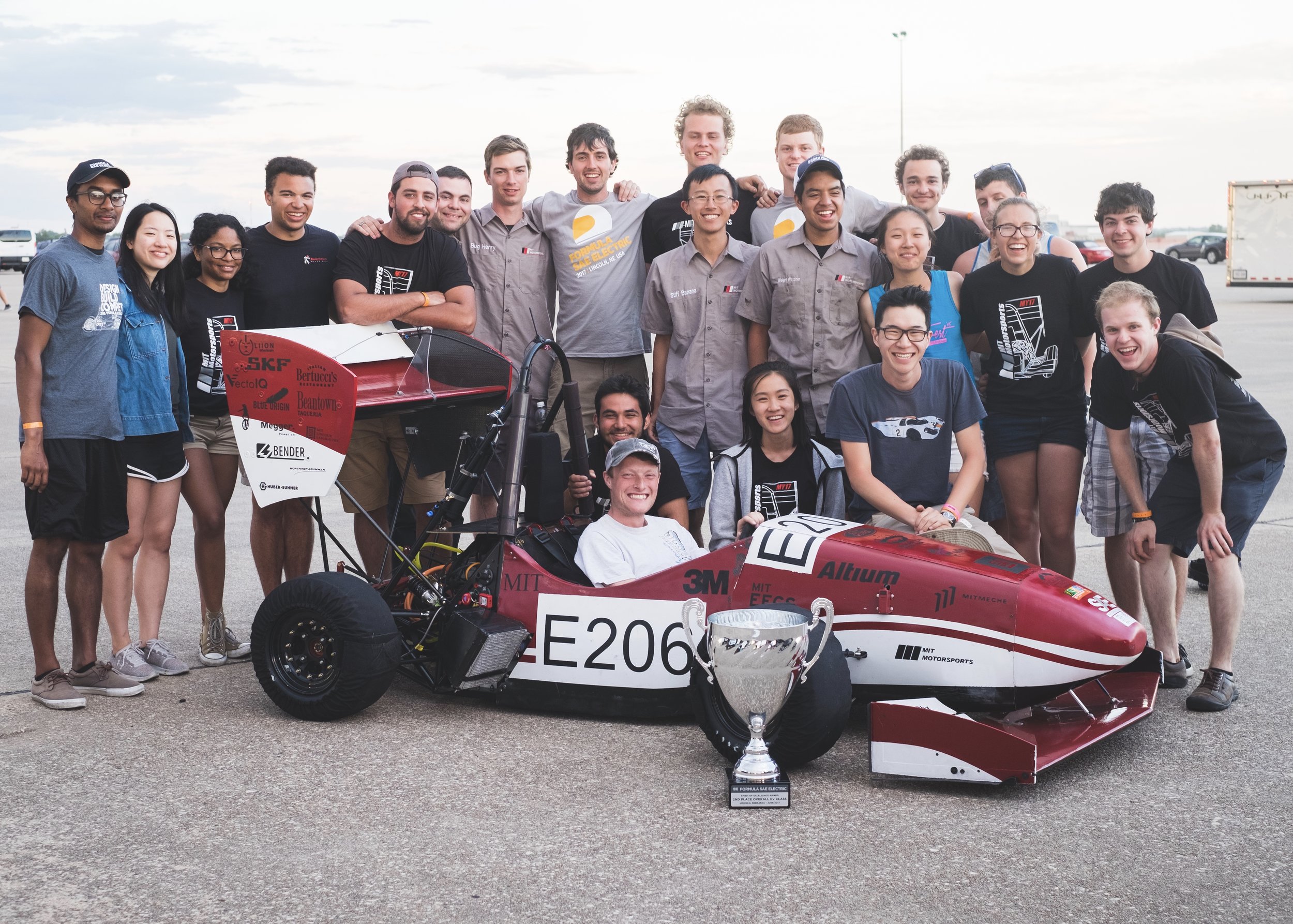
Each school year, MIT Motorsports designs, builds, and competes against other universities with a formula-style car in the Formula SAE competition series. My 3rd and 4th year of engineering design on the team focused on the suspension kinematics for the team’s ‘17 and ‘18 vehicles. We placed 2nd overall in the electric category at the US Competition with the 2017 car and set the fastest times in 3 out of the 4 dynamic events in 2018.


DESIGN
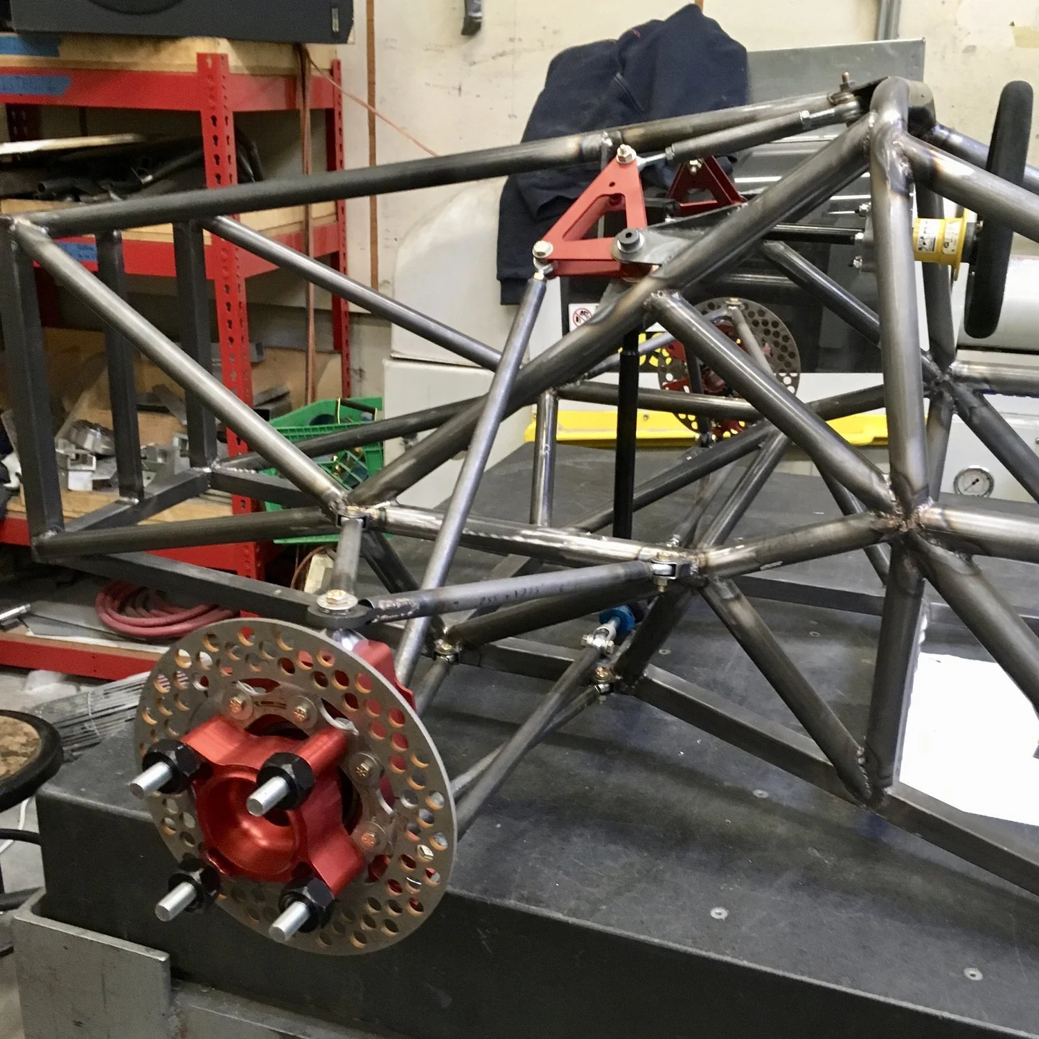
A car’s suspension is the system that serves as the interface between the vehicle’s chassis (frame) and tires. A well-designed suspension maximizes the tire’s grip by balancing hardware packaging with optimal kinematic geometry for the tire’s range of motion.
The goal of suspension kinematics is to minimize the vehicle’s roll center movement and to maximize the tire’s contact patch, which maximizes grip while turning. Maximizing grip allows the driver to complete each corner at a higher speed, yielding faster times through driving courses. Given that half of the competition is driving events, getting the kinematics right is vital.

Optimization
To tackle this, we aggregated the constraints for the chassis, A-Arm hardware, wheel uprights, brakes, and steering. This formulated a set of requirements at each suspension point to make the optimization achievable. The simulation interface (shown above) provided the information essential to finalizing a draft design through the different suspension positions seen during driving.
With each draft of the design, a successful clearance check using a full-car CAD model would yield a new suspension geometry iteration. These iterations were repeated as sub-system design changed to meet requirements until the design was frozen for manufacturing.


Above is one of the notable changes in geometry between 2017 and 2018. To produce a legal chassis in ‘18, the frame geometry changed, allowing the A-Arm to connect to the chassis at a lower position, which allowed the wheel package design to change (not shown) as well.

Competition
The Formula SAE Electric competition consists of judged design and dynamic events. The design events give teams a chance to showcase their vehicle development process from concepts and optimization to manufacturing and validation. After completing the design events, the focus shifts to the track with events testing the cars’ acceleration, agility, and endurance.
2017:
We decreased the vehicle’s wheel size to 10 inches to reduce the time required for the tires to reach operating temperature on MY17. Significant hardware interferences resulted from this change, but the change was validated because competition events do not allow time to warm the car up, which means that a smaller wheel is beneficial as it warms up quicker.
With everything in place, we placed 2nd overall in the FSAE Lincoln EV Competition after driving the fastest electric-powered lap of the Endurance segment of the competition.
2018:
The team’s goal for 2018 was to produce a robust vehicle through iteration upon the past and testing. The FSAE EV competition still sees fewer than 5 cars (out of ~40) finish all of the competition’s dynamic events, so our goal was a working car that we could optimize. A rules change for 2018 required a comprehensive study of tradeoffs between kinematic performance and packaging the frame, suspension, and wheel packages to ensure that undesirable characteristics, such as positive camber, did not occur when accommodating the new constraints.
Enabling the powertrain to efficiently drive the car, the design helped position our 2018 car as the fastest in the acceleration, autocross, and endurance events at competition.
Fast facts
We used WinGeo suspension geometry software to calculate the relevant angles and radii in the suspension across a range of steering and chassis roll conditions.
At the most basic level, the goal is to minimize negative camber at your maximum cornering load (maximum roll value) without camber becoming positive. You want the tires to be maximizing the contact patch when the car is at its maximum designed roll value (also at the edge of the g-g diagram/traction circle).
Bump steer can be designed out of the system, but these simulations can confirm that your engineering was done correctly to eliminate bump steer.
CAD interference checks were done in Solidworks with the full chassis and suspension mechanical models.
My senior thesis outlined the kinematic optimization process and is available at this link to the MIT library.
Further resources
Some useful papers by my teammates are FSAE vehicle model & simulation by Cheyenne Hua and FSAE vehicle dynamics, kinematics, and tires by Audrey Gaither
FSAE Resume Drop
Fill out the form below if you’d like your resume considered for summer internships or new grad hires when my team is looking for mechanical, electrical, and software interns.